ARGO System and Service Architecture
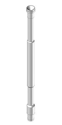
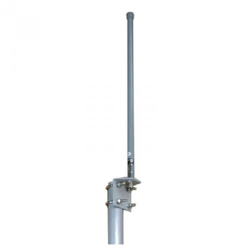
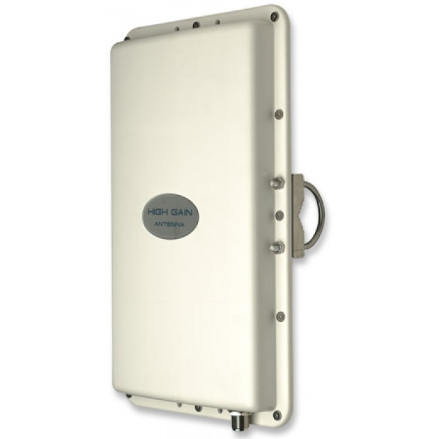
The ARGO patented
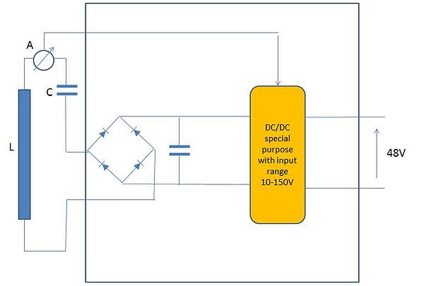
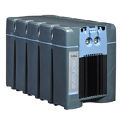
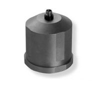
power supply is built around three main components: the LFA
magnetic antenna, the analog electronic circuit in charge of
transforming the energy into direct current, and a backup battery
to supply power to the service electronics in case of power line
outage due to malfunctioning or maintenance.
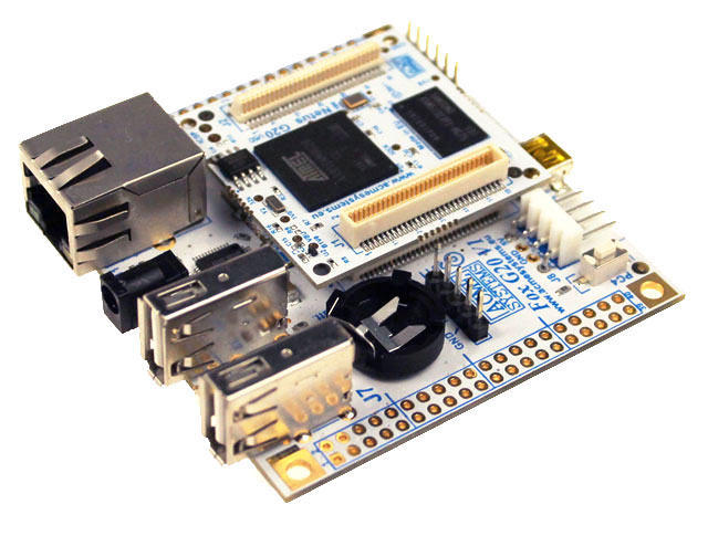
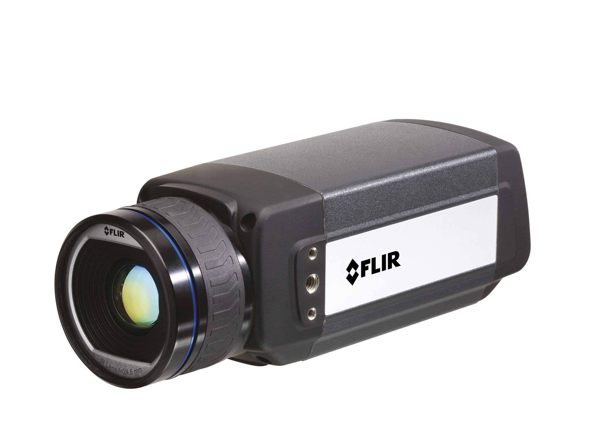
The power generated by the power supplies is sent to the service electronics which items configuration depends on the specific application. In addition to a series of basic electronic components required the remaining optional components depend on the application that the plant has to perform.
ARGO technology Strengths
Does not require additional energy sources such as photovoltaic panels, electrical cables or electric generators.
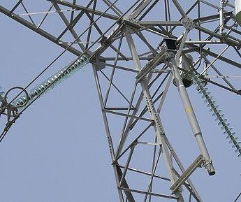
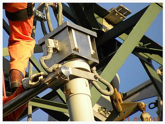
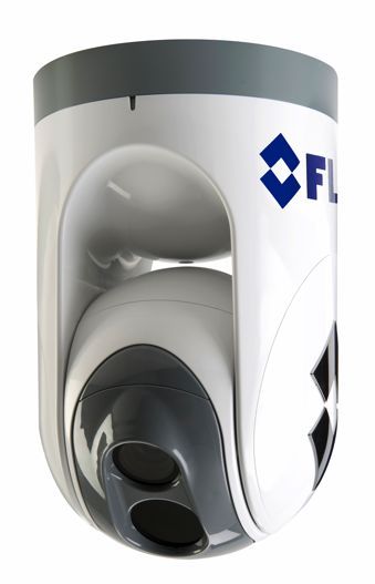
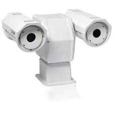
Independent from meteorological condition such as rain, snow, ice, hailstorm, wind, fog, sun and pollution.
Feeds the devices for days even in case of maintenance or failure of the power line.
High level of security against terrorist attacks or vandalism because protected by electric fields can not be joined by humans.
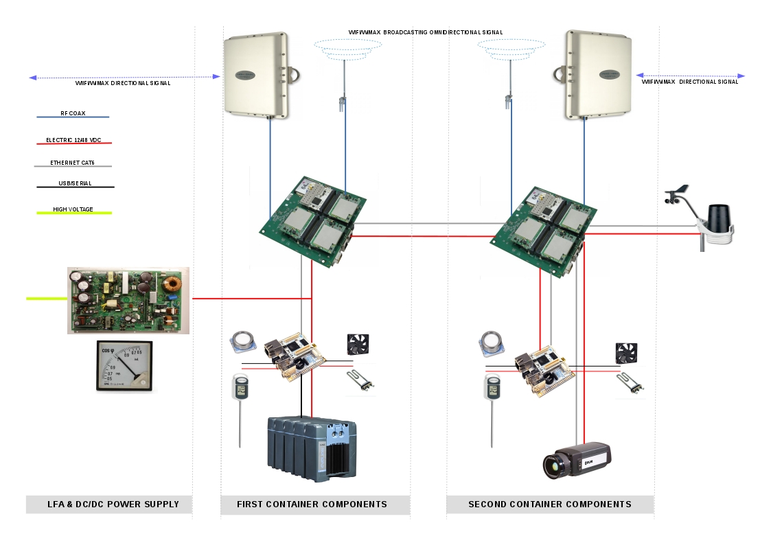
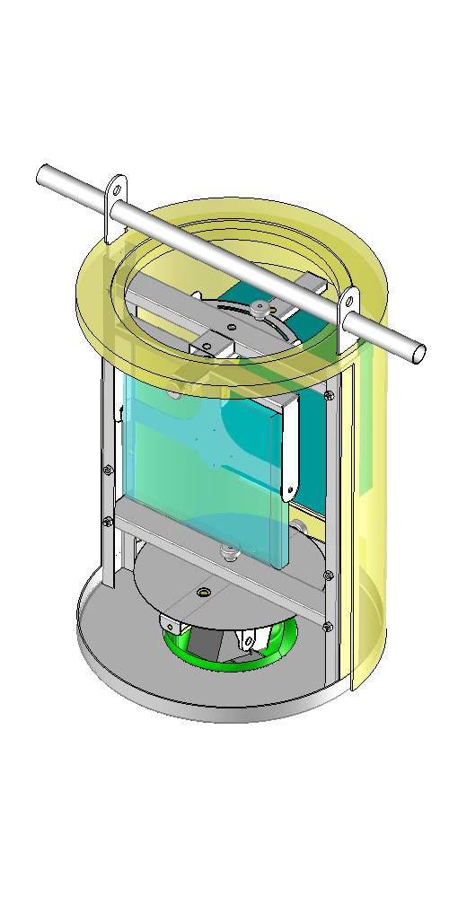
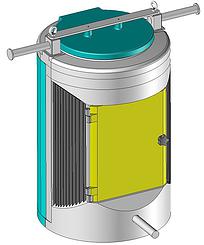
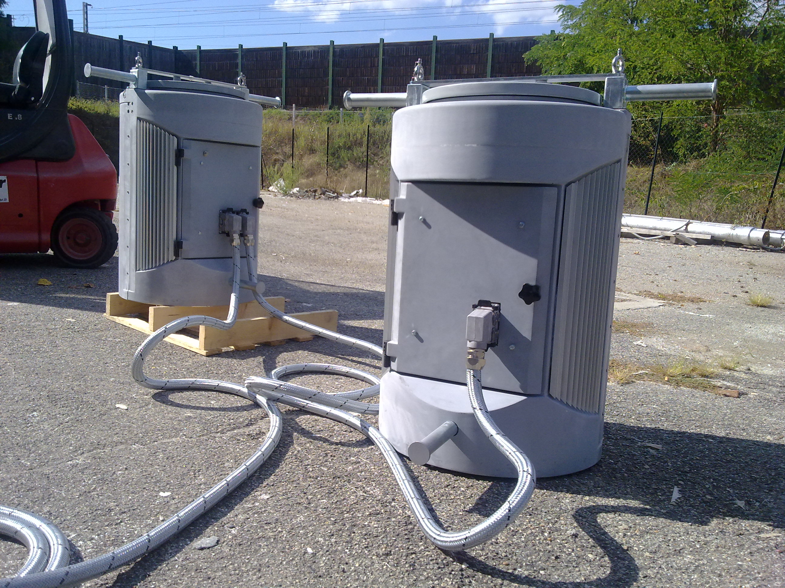
Electrical and Data Connections Schema of LFA - Power supply - First container - Second container
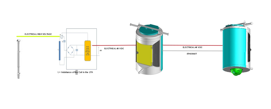
Components
Connections Schema
Below is shown the simplified schema of the architecture and functional connection of the internal container's components used in pilots plants.
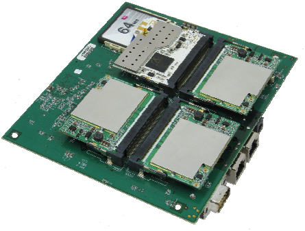
It is a
LAN formed by two nodes by the SBC Router/Switch.
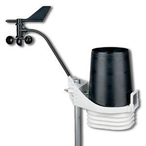
The second SBC Manager is used to periodically scan and control sensor devices and to activate actuator devices.
Example of theese are internal and external thermometer to warming or cooling the container.
Components
Descriptions
Low Magnetic Fields Antenna
LFA Magnetic Antenna
Antenna that harvest the magnetic component of the electro-magnetic field generated by electric network.
In the current version of the ARGO system, the magnetic antenna has a core built using a high tech magnetic material with top performances and very low losses. A revisited design aimed at reducing the size and weight of the antenna is being carried out, in order to simplify the installation and maintenance procedures in future versions of ARGO.
Connection
Cable
Protected Cable
This is the protected cable with power and data used to connect in chain all main components of the architecture.
Power Supply DC
Feeder
Power supply DC Feeder
The basic block diagram of the power supply (upper schema) is quite traditional, with a dynamic added control of the DC/DC behaviour based on the current flowing in the antenna L. Such control allows to prevent the saturation of the antenna core, optimizing the amount of energy "captured" from the magnetic field generated by the power line conductor(s)
Protected metallic box
In this photo is shown the the metallic cubical box positioned on the top of antenna containing the DC power supply
Service
Electronics
Containers
Protected Containers
The standard installation expected two containers. Above are the different cad-cam schematics and below the container couple just built for pilot and connected by protected cable.
The service electronics and the backup battery must be protected from the weather and other threats, so they are enclosed in the containers connected to the power supply subsystem through data and power cables. Like all other elements of the ARGO system, the containers are designed to be attached to the power line tower.
Pilot
Plants
Service Electronics
SBC
WIFI/WIMAX RF Router/switch
SBC service supervisor.
Wifi/wimax omni-directional
antenna.
Wifi/wimax directional
antenna.
FLIR Fixed thermo camera
Meteo station
Li-Ion industrial
Accumulator.
Some examples of potential service
electronics that may be used in future plants.
Pan Tilt branded via ip Optical and Thermo
Camera
High Resolution Optical and Thermo
Camera
Lite Meteo Station.
Satellite Communication Antenna.
3-Axial Sismic
Accelerometer
Copyright Tixon Energy srl (C) 2008 - 2016 - all rigths are reserved