ARGO technology
The technology developed by Tixon Energy s.r.l is an energy
harvesting system to be used in proximity of electrical power
lines.
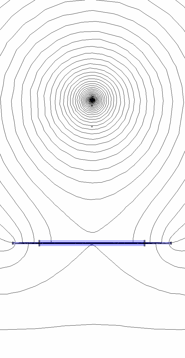
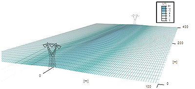
In the below left figure is rapresented the intensity by distance of the magnetic field generated between two pylons or electric towers in the Italy National Grid by Terna (C) Spa. In the below central and rigth figures are represented the force lines simutations of Magnetic and Electrical component field.
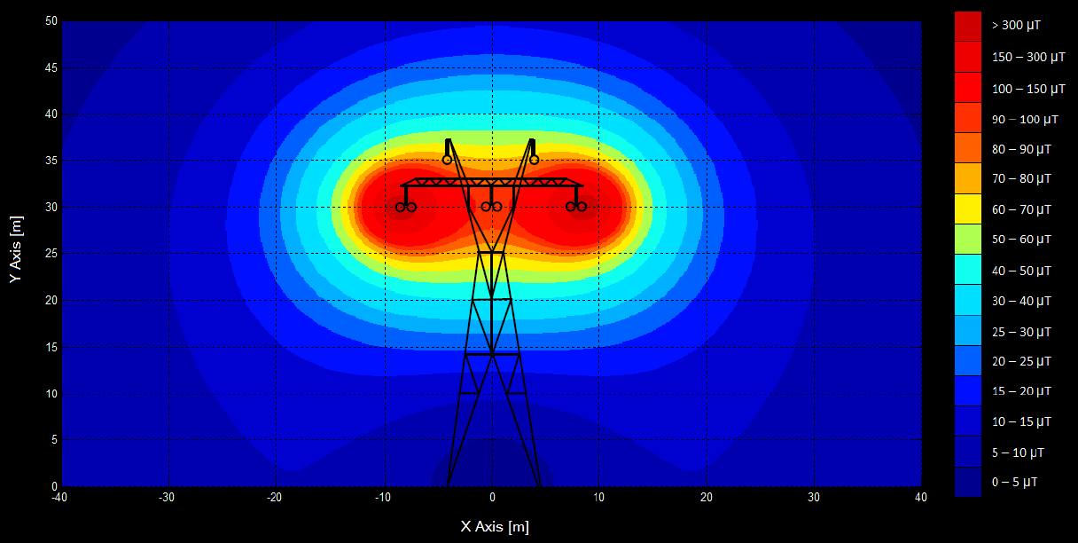
Magnetic Component Field Simulation
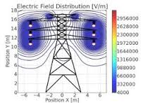
Electrical Component Field Simulation
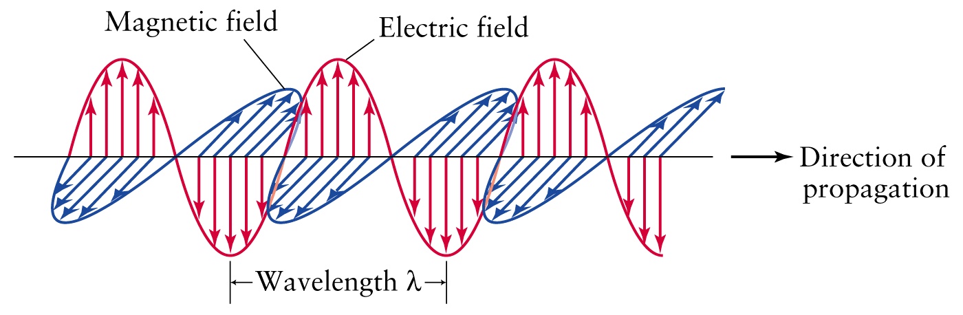
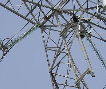
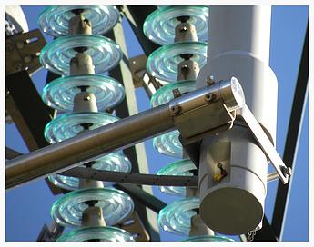
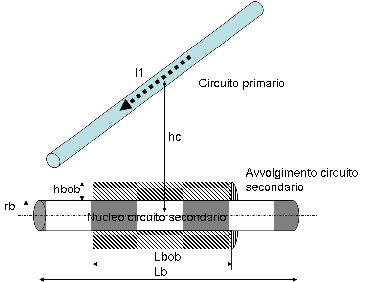
Once installed at the top of a
power line pylon, the system generates power from the magnetic
induction between the line conductors and a linear
Low frequency/magnetic Field
intensity Antenna (LFA)
positioned at safety distance (1÷5 m) from them.The resulting
system is a very loose coupled transformer, where the primary
circuit is represented by the power line, and the secondary circuit
is represented by the LFA magnetic antenna.
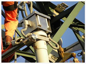
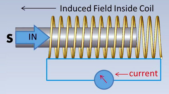
Cascaded to the antenna is a
sophisticated electronic module generating DC power output. The
patented operational principle of this device is keeping under
control the level of saturation of the LFA magnetic core, therefore
continuously guaranteeing the optimal harvesting efficiency for
different service electronics load consumption.
After being transformed in a more usable DC
format, the energy generated by the antenna + power supply system
it is used both to power the service electronics and to charge a
li-ion accumulator.
Principles of Electromagnetic Fields
The cables (whose direction is indicated as Direction of propagation) that carry electricity generating an electromagnetic field whose electric and magnetic components are out of phase by 90° as in the figure below where are shown the magnetic and electrical fields amplitudes.
The amplitude over time of the electrical component is proportional to the electrical voltage (Volt) while the amplitude of the magnetic component is proportional to the intensity of the electric current (Ampere) in the cable.
The ARGO technology sees only the magnetic component (blue wave in the figure) so the amount of energy extracted depends only by the intensity of the current present in the cable, the wavelenght is fixed based on reverse of industrial frequency that is 50 Hz.
The electrical component instead constitutes a potenzial danger for the plant but is removed maintaining the LFA remote from the cable (1-5 meters dependig of voltage) futhermore the LFA is kept at a 1m distance from the pylon structure to minimize the effects of the metal structure of the pylon on the magnetic field (the antenna best performance is obtained when there is no metal surface close to it).
In the below photos you can see the position of the LFA relating to the electrical cable and to the tower.
In the below
photo a detail showing the electronic power supply attached to the
top of the magnetic antenna (picture taken during a field test
installation) The cubic box attached at the top of the antenna
protects the power supply electronics which transforms the highly
inductive energy caught by the antenna in a more usable DC
form.
Low Field Antenna, coupling the primary circuit to the secondary circuit
In
electrical engineering is defined as the primary circuit (fig.
Circuito primario) the cable of power line while is referred as the
secondary winding of the coil (fig. Avvolgimento circuito
secondario) in the device LFA
antenna.
In the left below figure is rappresented the physical proximity of grid power cable (fig. Circuito primario) flowed by I1 intensity current to the secondary circuit consisting of core and winding (fig. Nucleo circuito secondario - Avvolgimento circuito secondario).
In the right below figure are rappresented the magnetic field lines generated by power cable that is figured as its section (single black point of cable perpendicular to your screen). The magnetic field penetrate the below LFA antenna horizontal in the figure.
The
sinusoidal magnetic field of the primary circuit coil (a theorical
loop of infinite radius) induces a sinusoidal magnetic field inside
the coil of secondary circuit contained in the LFA antenna. This
induced field in turn generates across the coil a potential
difference that applied to a load ( power supply ) generates a
current.
The induced current is then
rectified and stabilized by the DC power supply which feeds both
the service electronics and the battery of lithium ion used as a
buffer battery in case of maintenance of the power line.
Copyright Tixon Energy srl (C) 2008 - 2016 - all rigths are reserved